![<?echo $_SERVER['SERVER_NAME'];?>](/template/twentyseventeen/skin/images/header.jpg)
Vera CAD supports the CAD system currently in use. Vera CAD has basic geometry manipulation features such as mirroring, rotating, deleting, or zooming in and out. The design of the final roll blank is also included in the mass distribution diagram, but its shape needs to be as simple as possible. For curved parts, the curved multi-shaped line is alternately input, which is usually the center line of the geometry, and the calculation of the mass distribution map is indicated by line 1. For symmetrical parts, there is very little man-machine dialogue, but for curved parts, you need to input multi-shaped lines or modify the data. After fully calculating the mass distribution, obtain the two-dimensional mass distribution curve, and change the length coordinate to show the cross-sectional area. The X axis is the multi-shaped line shown by line 1 (see Figure 4).

Vera CAD assists the designer in simplifying the mass distribution of the final roll blank, clearly indicating possible underfilled areas or areas of excess material. Line 1 in Figure 4 indicates the mass distribution of the final roll blank. The 3D animation is used to check that the simplified final roll blank conforms to all the mass distribution characteristics of the original CAD geometry. This inspection facilitates the discovery of defects that may occur in roll forging dies or roll forging blanks at the beginning of the design. The final roll blank can have cross-sections of various shapes, such as a series of round and square blend patterns displayed by the link sample; or you can choose to manually create or edit the geometry of the final roll blank. In the case where the roll blank has no three-dimensional geometry, the roll blank pattern can be input using the final roll blank editor, but at least a two-dimensional sketch of the main dimensions is required.
The basic forms of raw materials imported by Vera CAD are both circular and square. The Vera CAD calculation generates a standard solution that automatically calculates the required roll forging pass, cross section, shape and corresponding shrinkage. Designers can accept parameters in this or modification program, such as roll forging passes, which helps designers reduce passes and reduce tooling costs. The editorial nature of standard solutions offers diversity. Each time the parameters are modified, Vera CAD refreshes the screen so that the modified pattern is displayed visually and clearly. The roll forging long blanks take into account the blanks produced by the roll forging process during the design process, and the use of the guide grooves particularly eliminates the defects of the roll blanks.
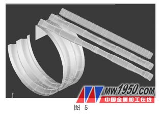
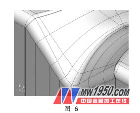
Generating geometry is a key feature of Vera CAD. After completing the standard scheme, the command automatically generates a three-dimensional intermediate transition roll blank for each pass (see Figure 5). In order for the material volume to remain constant throughout the deformation process, an accurate calculation of the volume of the material is required. The 3D CAD surface pattern of the roll blank facilitates the use of projection or wireframe models to estimate standard solutions and will quickly reveal defects in the roll blank. The 3D geometry shown in Figure 6 is the basis for CNC machining of the mold CAC.
Vera CAD has no special requirements for roll forging equipment. It can provide roll forging die parameters according to user's standard. Different molds can have different width, angle and roll exit radius. It also allows the use of old or reworked molds, which helps to reduce the mold. cost. A large number of multi-mesh cavity surfaces were detected using a CAD system. Vera CAD's 3D geometry is available for CAE CNC milling. Vera CAD's diverse plate model is used to inspect and demonstrate the design of the mold. Prior to production, important design parameters can be referenced to facilitate the final improvement of the mold.
Among the domestic forging enterprises, Baicheng Zhongyi Precision Forging Co., Ltd. and other companies used Vera CAD software for the design of roll forging die in the early stage of actual production design, and achieved satisfactory results.
4. Conclusion
As a representative of forging simulation software, Vera CAD can help engineers avoid the cumbersome design calculations when designing roll forging dies, saving design time and enabling complex roll forging dies to be completed in a short time. It has a positive driving effect on improving the accuracy of the mold design and the stability of the design process, shortening the product design cycle, reducing the development cost, and adapting to the market.
Previous page
Children Toy Mould,Plastic Toy Mould,Toy Mould
Pipe Fitting Mould CO.,Ltd , http://www.gosmould.com