![<?echo $_SERVER['SERVER_NAME'];?>](/template/twentyseventeen/skin/images/header.jpg)
Foreword
This section was drafted following the rules given in GB/T 1.1-2009.
This section is proposed and managed by the Department of Science and Technology, Ministry of Agriculture of the People's Republic of China.
This section mainly drafted by: China Rural Energy Industry Association Small Power Professional Committee, China Lighting Association New Energy Lighting Professional Committee, Beijing Ai You En New Energy Technology Research Institute, Beijing Liangye City Lighting Energy Saving Technology Co., Ltd., Beijing City Sunlight Technology Co., Ltd., LeLei Optoelectronics Technology (Shanghai) Co., Ltd., Beijing Sangpu Optoelectronics Technology Co., Ltd., Hebei Greentech Optoelectronics Technology Co., Ltd., Huangshi Dongbei Electromechanical Group Solar Energy Co., Ltd., Yangzhou Kaiyuan Solar Lighting Technology Co., Ltd.
The main drafters of this section: Li Anding, Wu Chuyu, Zhu Weigang, Li Xiaohui, Zhang Hao, Sun Peiyu, Zhang Feng, Cao Chunfeng, Fang Fengjie, Zhou Qingshen.
1 Scope
This standard specifies the classification of solar photovoltaic outdoor lighting devices, device components and technical requirements, the overall device requirements, test methods, inspection rules and signs, packaging, transportation and other requirements.
This standard is applicable to solar photovoltaic outdoor lighting devices for lighting in public places such as roads, courtyards and squares in rural villages and villages in China.
2 normative references
The following documents are indispensable for the application of this document. For dated references, only dated versions apply to this document. For undated references, the latest version (including all amendments) applies to this document.
GB/T 191 packaging, storage and transportation logo (eqv 1S0780:1977)
GB/T 2828.1 Count Sampling Inspection Procedures Part 1: Batch Inspection Sampling Plans Retrieved by Acceptance Quality Limit (AQL) (IS02859.1:1999, IDT)
GB/T 2829 periodic inspection counting sampling procedure and sampling table (applicable to the stability inspection of production process)
GB/T 5700 lighting measurement method
GB 7000.1 Lamp Safety Requirements and Tests (IEC 60598-1:1999, IDT)
GB 7000.5 Safety requirements for street lighting and street lighting fixtures (idt IEC 598-2-3:1993)
GB/T 9535 surface crystalline silicon photovoltaic module design identification and finalization (eqv IEC 1215:1993)
Performance requirements for AC electronic ballasts for GB/T 15144 tubular fluorescent lamps (IEC 60929:2000)
GB/T 18911 Design and identification of thin-film photovoltaic modules for ground use (idt IEC 61646:1996)
GB/T 19064 Home solar photovoltaic power system technical conditions and test methods
GB 19510.5 Lamp control apparatus Part 5: Particular requirements for dc electronic ballasts for general lighting (IEC 61347-2-4: 2000, IDT)
GB/T 19638.2 Fixed valve-regulated sealed lead-acid batteries
GB/T 19639.1 Technical requirements for small valve-regulated lead-acid batteries
GB/T 19656 Performance Requirements for DC Electronic Ballasts for Tubular Fluorescent Lamps (IEC 0925:2001, IDT)
3 Terms and Definitions
The following terms and definitions apply to this document.
3.1
Solar PV lighting devices for outdoor use
A solar device, a battery, a lighting component, a controller, and a mechanical structure are combined to use solar energy as an energy source and an outdoor lighting device for off-grid use.
3.2
Solar cell module solar cell module
With a package and internal connection, can provide a separate direct current output, the smallest integral solar cell combination.
3.3
Charge and discharge controller
A control device that automatically controls the solar cell array to charge the battery and the battery discharges to the lighting component.
3.4
Road lighting luminaires for road lighting
Functional lighting used in road lighting. According to its distribution into light-cutting, half-cut type and non-light-cutting lamps.
3.5
Luminaire efficiency
Under the same conditions of use, the ratio of the total luminous flux emitted by the lamp to the total luminous flux emitted by all the light sources in the lamp.
3.6
Semi-cut-off luminaire
The luminaires with the maximum light intensity and the downward vertical axis angle of the luminaire between 0° and 75° and the maximum allowable light intensity in the 90° and 80° directions are 50cd/1000 lm and 100cd/1000 lm, respectively. And regardless of the size of the light flux of the light source, its maximum value in the 90° direction should not exceed 1000 cd.
3.7
Non-cut-off lamps non-cut-off luminaire
The direction of the maximum light intensity of the lamp is not limited, and the maximum intensity of the light in the direction of 90° should not exceed 100 cd.
4 device classification
Solar photovoltaic outdoor lighting devices are divided into street lamps and garden lamps according to their purposes and places of use.
4.1 Rural Solar PV Street Lights
There are lighting for townships, village streets, and tourist attractions.
4.2 Rural Solar PV Garden Lights
Outdoor public places, courtyards, residential areas, leisure areas, and pedestrian roads, etc. for lighting.
5 device component technical requirements
5.1 Solar Modules (Solar Optoelectronic Conversion Units)
The technical performance of crystalline silicon solar cell modules should meet the requirements of GB/T 9535; the technical performance of amorphous silicon and other thin film solar cell modules should meet the requirements of GB/T 18911.
5.2 Battery (energy storage component)
Should choose valve-regulated lead-acid batteries, its performance should be consistent with GB/T 19638.2 or GB/T 19639.1; select other types of energy storage components, its performance should meet or better than GB/T 19638.2 or GB/T 19639.1 Relevant regulations.
5.3 control components (charge and discharge controllers, etc.)
a) The performance of the charge-discharge controller shall comply with the provisions of 6.3.2-6.3.13 of GB/T 19064-2003;
b) The device should use DC power supply, but also can use AC inverter power supply;
C) In case of AC power supply, the configured inverter shall meet the relevant requirements of GB/T 19064.
5.4 Electric Light Sources and Accessories and Luminaires (Lighting Components)
a) The safety requirements and performance requirements of electric light sources should comply with relevant national standards;
b) DC electronic ballasts for gas discharge lamps shall comply with the provisions of GB 19510.5 and GB/T 19656;
c) AC electronic ballasts for fluorescent lamps shall comply with the provisions of GB/T 15144;
d) The safety performance of the luminaire shall comply with the requirements of GB 7000.1 and GB 7000.5.
5.5 Lamp Posts, Solar Cell Assembly Holders, etc. (Structural Parts)
a) If steel poles and solar cell module holders are made of steel components, hot-dip galvanizing, plastic spray and other anti-corrosion treatments shall be used; if other material components are used, the relevant national standards shall be complied with;
b) After the solar cell module holder, lamp and lamp post are combined, the overall technical requirements of the device shall be met.
5.6 Connection cable
The choice of cable shall satisfy: The current shall not be greater than the allowable current carrying capacity of the cable, and the voltage loss shall meet the requirements of 6.3.3; the cable shall meet the mechanical strength requirements.
6 overall performance requirements of the device
Application Environment
Should be able to work within the temperature range of -20 °C to 50 °C (manufacturers should reasonably set the lower temperature limit according to the climatic conditions of the application area and user needs).
6.1.2 It should be able to work normally when there is 3-n continuity (the manufacturer can set the upper limit n according to the conditions of the application area) in yin, rain and snow days.
6.1.3 Solar modules should not be covered by any objects or shadows at all times during the sunshine.
6.2 Security Requirements
6.2.1 should be able to withstand wind loads above s level (manufacturers can set wind load levels based on the conditions of the application area).
6.2.2 should have good waterproof, anti-corrosion, moisture-proof, anti-pollution measures.
6.2.3 The insulation resistance between the live parts of the device and the metal parts of the device shall not be less than 2 MΩ.
6.2.4 Special tools should be used for assembly and disassembly. The controller room and battery room should be equipped with anti-theft measures.
6.2.5 The controller room should be more than 200mm above the ground.
6.2.6 Short-circuit protection should be installed between the battery and the controller.
6.3 Performance Requirements
6.3.1 Device Appearance
a) The device should be treated with anti-corrosion treatment. The surface should be smooth, smooth and free of scratches;
b) The solar module tilt angle and azimuth angle setting should be able to obtain the annual average maximum sunshine temperature in the area.
6.3.2 Charge and Discharge and Lighting Control Methods and Requirements
a) The device charge and discharge controller requirements see 5.3;
b) light control, time control or a combination of both;
C) Time-controlled opening and closing time should be adjustable, and the time error range when turning lights on and off should not exceed 5 min;
d) The light control value should be set when the natural illumination of the ground is 51x-10lx;
e) It has measures to prevent the light source from being repeatedly turned on and off when the light source is turned on or off.
6.3.3 Line Voltage Loss on Charge and Discharge Lines
a) When the solar cell module charges the battery through the controller at rated current
The line voltage loss between the output end of the solar cell module and the input end of the controller should not exceed 3% of the rated voltage of the battery.
b) When the storage battery discharges the lighting components under rated conditions
The line voltage loss between the battery output terminal and the controller's battery input terminal should not exceed 1% of the battery's rated voltage.
The voltage loss between the output of the controller and the lighting component input should not exceed 3% of the rated voltage of the battery.
6.3.4 Continuous discharge capability of the device
In the continuous 3-n (the manufacturer set the upper limit n according to the conditions of the application area) a day of rain, rain, snow, should be able to provide normal lighting every day.
If the device continues for n rainy days, the storage capacity of the battery needs to be maintained ((n ± 1) d;
The discharge depth of the battery should not exceed 75%.
6.3.5 Mounting height of light sources, accessories, lamps and luminaires of the device
a) Rural solar photovoltaic street light
Should choose high pressure sodium lamp, metal halide lamp, low pressure sodium lamp, LED lamp and other light sources;
Should choose half-light type lighting fixtures, lamp size should be matched with the light source power, the lamp protection level should not be lower than IP54;
Lighting efficiency should not be less than 70%;
The lamp installation height should be 4m-8m.
b) Rural solar photovoltaic garden lights
Should choose to use self-ballasted fluorescent lamps, IJED lamps and other light sources;
Non-cut-off lamps can be used, the lamp protection level should not be lower than IP54;
Lamp installation height should be 2.5m-4m.
C) DC electronic ballasts for gas discharge lamps must have constant power output characteristics
Fluorescent lamp DC electronic ballasts must have good warm-up, filament warm-up start time should not be less than 0.4s.
d) Luminous efficiency of electric light sources for devices
The luminous efficacy of self-ballasted fluorescent lamps and LED lamps should not be lower than 50Lm/W;
The luminous efficacy of high-pressure sodium lamps, metal halide lamps, and low-pressure sodium lamps should not be lower than 60 Lm/W.
e) Lifetime of the device light source
High pressure sodium lamps, metal halide lamps, low pressure sodium lamps, self-ballasted fluorescent lamps should not be less than 8000h;
LED lights (including matching appliances) should not be less than 20000h.
f) The lamp post height of the device shall meet the mounting height of the lamp and the installation requirements of the solar cell assembly at the same time.
7 test methods
Tests are divided into component tests and complete machine tests.
7.1 Component Test
Parts should be tested in compliance with the relevant standards tested in accordance with 5.1-5.6 and qualified.
7.2 overall test
The whole test is passed after the parts are inspected and assembled.
7.2.1 Appearance
Use visual, touch and micrometric calipers, ruler measurements and other methods to test.
7.2.2 Insulation resistance
The insulation resistance between the conductive part and the steel pole was measured with an insulation resistance meter.
7.2.3 Charge and Discharge and Lighting Control
a) Automatic charge and discharge control: According to the provisions of GB/T 19064-2003 6.3.2-6.3.13.
b) Lighting control
Light control plus time control: light control turn on the light, use the illuminometer to measure the natural light level value of the ground when turning on the light;
When the lights are turned off, they should be adjusted according to the season and the lighting time should be measured with a timer.
Time control: The time for turning lights on and off should be adjusted according to the season. The lighting time is detected by a timer.
Illumination control: Use the illuminometer to measure the natural illuminance of the ground when the device is turned on or off.
7.2.4 Voltage Loss of Charge and Discharge Lines
The line voltage drop of the device is checked with a 0.5-level DC voltmeter, ammeter, and calculation method:
a) During charging, measure the line voltage loss of the cable from the output terminal of the solar module to the controller's charging input terminal.
Disconnect the cable from the output of the solar module and connect the cable to an adjustable voltage regulator.
Disconnect the cable from the controller to the input terminal and connect the cable to the adjustable load.
Adjust the adjustable voltage supply voltage to the rated voltage value of the solar cell module, adjust the adjustable load, make the output current of the solar cell module its rated current value, measure the voltage of the adjustable load, the voltage and the voltage of the adjustable voltage regulator The voltage difference is the line voltage loss of the cable.
b) During discharge, measure the loss of the line voltage from the battery to the controller input terminal; the output from the controller to the lighting component input cable.
Disconnect the battery cable and connect the cable to an adjustable voltage regulator.
Through the controller to make the lighting device work under rated conditions 1h;
The value of the input voltage of the controller is measured, and the difference between it and the adjustable regulated supply voltage is the loss of the cable from the battery to the controller. Loss of voltage on the cable: Measure the output voltage of the controller and lighting components (inverter supply, With the inverter input voltage, the difference is the line voltage loss of the cable.
7.2.5 Continuous discharge capability of the device
Under normal conditions of use, the battery is fully charged and the solar module is disconnected and tested as follows;
The depth of discharge of the battery within every N hours (N: lighting time of the device per day) is not greater than [75/(n+1)] % (n: days of rainy days).
7.2.6 Wind load
The manufacturer shall provide design calculation instructions for the installation to withstand the wind loads specified in 6.2.1.
8 inspection rules
8.1 Inspection Classification
Inspection is divided into factory inspection and type inspection.
8.2 factory inspection
Performed according to the provisions of GB/T 2828.1. With one sampling, the project, inspection level and quality level of conformity shall meet the requirements of Table 1.

8.3 type test
Performed according to the provisions of GB/T 2829. With a one-time sampling plan, the conditions for the project and passing judgment shall comply with the requirements of Table 2.
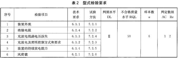
Samples are randomly selected from products that have passed the factory inspection.
If the type test fails, the batch is unqualified. The production and acceptance should be stopped immediately.
Measures shall not resume production and acceptance until the new type inspection is passed.
Type inspection is not less than once a year. A type test should be performed when one of the following conditions occurs:
a) At the time of product qualification test;
b) Stop production for more than half a year and resume production;
C) When design, process or material changes may affect its performance;
d) When the quality and technical supervision department puts forward the inspection.
9 signs, packaging, transportation
9.1 mark
The device should have the following clear and firm signs:
a) product name, model, trademark;
b) Specification and model of supporting solar cell modules, batteries and electric light sources;
c) Manufacturer, date of manufacture.
9.2 Packaging
a) Each part of the device should be separately packaged, and the packaging box should meet the relevant standards;
b) Outside the box should be "upward", "careful light release", "moisture-proof", "stacking number limit", etc., shall comply with the provisions of G/T 191;
C) The packing box should have documents such as parts list, installation instructions, product certification, user manual and maintenance management requirements.
9.3 Transportation
a) The requirements for loading, unloading and transport and the protective conditions during transport should be stated in the conditions of transport and precautions;
b) Rain and snow shall be prevented from attacking and vibrating strongly.
Ningbo RMI Plastic Co.,Ltd offer several models of CPVC Check Valve, include flange type Swing Check Valve, socket type swing Check Valve ,CPVC flange Ball Check Valve, CPVC true union ball check valve, CPVC single union ball check valve, CPVC Wafer Check Valve, CPVC Foot Valve socket end, CPVC bottom valve flange end. designed as per standard DIN, ANSI, JIS, BS, CNS. pressure rate by PN10. CPVC check valve is usually used in chemical industrial for acidic and alkaline medium delivery
Ningbo RMI Plastic Co.,Ltd offer CPVC check valve with specification:
Size:DN15~DN300 (1/2 inch ~ 12 inch)
Connection: Flange DIN PN10, ANSI CL150, JIS10K; socket DIN, ANSI, JIS, CNS, BS; Thread BSPT, NPT.
Body Material: CPVC
Seal material: EPDM;FPM
Design pressure:1.0Mpa(PN10 bar)
CPVC Check Valve
CPVC Check Valve,CPVC Swing Check Valve,CPVC Ball Check Valve,CPVC Wafer Check Valve
Ningbo RMI Plastic Co., Ltd. , https://www.rmiplast.com