![<?echo $_SERVER['SERVER_NAME'];?>](/template/twentyseventeen/skin/images/header.jpg)
This paper introduces the finite element modeling and analysis process of the machine tool table pallet based on Pro/MECHANICA, and compares the analysis results with the analysis results of the commonly used general finite element analysis software ANSYS. Through comparison, it is concluded that finite element engineers can use Pro/MECHANICA software to achieve seamless integration of solid modeling and finite element calculation, and can guarantee the calculation accuracy of finite element analysis and improve the efficiency of design engineers.
I. Introduction
Machine tool supports (such as bed, column, pallet, etc.) are the basic components of the machine tool, which can withstand the force and accommodate various components. The dynamic performance of the support directly affects the precision and production efficiency of the machined workpiece. Therefore, it is required that the machine tool support must have sufficient dynamic and static stiffness.
For a long time, machine tool supports at home and abroad generally use empirical design, but in order to ensure that the machine has good dynamic and static performance, and to reduce its weight as much as possible, it is necessary to carry out precise theoretical calculations. Machine tool supports are complex in structure and no precise method has been found to calculate their dynamic performance. But with the development and widespread application of computing and computer technology, engineers can rely on numerical methods to give approximate, more satisfactory answers. At present, among many methods, the mathematical model of mechanical analysis of mechanical systems with finite elements has become the most important method in theoretical modeling. Although the finite element method is also an approximate calculation method, the calculation accuracy is not very high for some support members with complex structure, stress and damping conditions, but it is still the most effective for calculating the dynamic performance of the support. Methods. At present, it is used to calculate the dynamic performance of the support of general complexity, and it is possible to obtain satisfactory calculation results.
Here, we will use the finite element software developed by PTC in the United States, Pro/MECHANICA to carry out finite element analysis on the carriage in the machine support, calculate the natural frequency and vibration mode of the part, and make necessary preparation for analyzing the surface vibration response of the carriage. It also provides a theoretical basis for the design of support parts such as machine pallets, bed bodies and columns.
Second, the current commonly used finite element analysis software and its characteristics
At present, the finite element analysis of mechanical parts generally uses general finite element analysis software, such as ANSYS, MARC and so on. They have a rich and complete cell library, material model library and solver, and have relatively independent front and back processing modules, which can independently complete multi-disciplinary and multi-domain engineering analysis problems. The disadvantage is that the geometric modeling function in the pre-processing module is not strong enough to complete the modeling of the complex model, thus reducing the credibility of the structural analysis results. Some popular 3D design software has powerful modeling tools for geometric models such as Pro/ENGINEER, UG and CATIA. These 3D design software can perform modeling of some complex geometric models. In order to overcome the shortcomings of the general finite element analysis software modeling function, data conversion between software is generally adopted, that is, accurate three-dimensional modeling is performed by using three-dimensional design software, and the model is read in IGES, DXF or STEP format through a standard data interface. Into the general finite element analysis software, and then through the software for accurate calculations.
In the process of model conversion, there are often some problems. Especially after converting some complex models to finite element software, there will be some problems such as loss of face and line and inability to mesh some features in the model. Therefore, after the model is converted, it takes a lot of time and effort to perform geometric model repair work in the finite element software, which inevitably leads to inconsistency of the model and increases the workload. Although some finite element software has developed a complete data interface, it can accurately import most of the geometric models generated on the CAD platform into the finite element software, but the simultaneous use of the two softwares puts more emphasis on the software and hardware of the design platform. High demands will greatly increase the economic burden of some SMEs.
Through comparative analysis of various finite element software, we found that Pro/MECHANICA can achieve complete seamless integration with Pro/ENGINEER, which can directly use the geometric model generated by Pro/ENGINEER for finite element analysis. Because Pro/ENGINEER has powerful parameterization functions, Pro/MECHANICA can use this advantage to perform sensitivity analysis and optimization design of the model. Specifically, when one or more parameters of the model change within a certain range, an optimal geometric model that satisfies certain design indexes (such as minimum mass, minimum stress, etc.) is solved.
Third, the establishment and calculation of the finite element model of the machine tool carriage
1. Establish a geometric model
The analysis here is the X-direction carriage of a CNC high-speed milling machine. This machine is used for roughing large modulus and large diameter gears. Due to the complexity of the structure of the carriage, Pro/ENGINEER software was used for 3D solid modeling.
The machine tool pallet geometry model established by Pro/ENGINEER software is shown in Figure 1.

Figure 1 Geometric model of the carriage
2. Define material properties
Machine tool pallets are important components in machine tool supports. They must withstand the enormous pressure of the table and workpiece during operation and must have high strength. Therefore, the material is selected as gray cast iron HT250. According to the relevant data, the mass density of HT250 is 7340; the elastic modulus is 1.55e11; the Poisson's ratio is 0.27.
In the menu manager [Parts], click the [Settings] → [Material] command option, and define the above material properties.
3. Define constraints
The carriage slides on the guide rail, and the guide rail constrains the movement of the carriage in the Z direction and the rotation around the X and Y axes. The screw seat constrains the translation of the carriage in the Y direction, and the pressure plate between the carriage and the guide rail restricts the translation of the carriage in the X direction and the rotation in the Z direction.
In the MEC STRUCT menu, select Constraints→New→Surface, and define the above constraints in the definition dialog box that pops up, as shown in Figure 2.
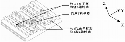
Figure 2 Constraints imposed on the carriage
4. Divide the grid
In the MEC SRTUCT menu, select the MESH menu option to define and divide the grid, and check the quality of the mesh. The grid that does not meet the requirements will be displayed in red in the finite element mesh model. The finite element mesh model of the carriage is shown in Figure 3.
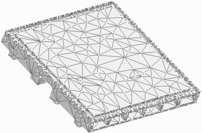
Figure 3 finite element mesh model of the carriage
5. Establish analytical tasks for finite element calculations
Select Analyses/Studies in the MEC STRUCT menu, and select File→New Modal... in the Analyses and Design Studies dialog box that pops up. The modal analysis task definition dialog box pops up, and the analysis task is set in this dialog box. Analysis calculated.
Fourth, the machine finite element modal analysis results
For the solution of the finite element model of the machine tool, it is generally not necessary to find the full natural frequency and mode shape of the vibration system. Since the low-order mode has a great influence on the vibration system, only the first three modes are calculated. At the same time, in order to verify the correctness of the finite element software Pro/MECHANICA for the modal calculation of the machine tool parts, this paper uses the current popular general finite element analysis software ANSYS to calculate the finite element mode of the machine tool carriage, and calculate the first three orders. The natural frequency and mode shape are compared with the calculation results of Pro/MECHANICA. The pair of natural frequencies is shown in Table 1, and the comparison of the first three modes is shown in Figure 4.

a) Pro/ENGINEER first-order mode diagram
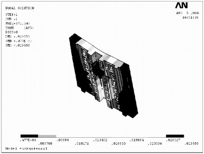
b) ANSYS first-order mode map

c) Pro/ENGINEER second-order mode map

d) ANSYS second-order mode map

e) Pro/ENGINEER third-order mode
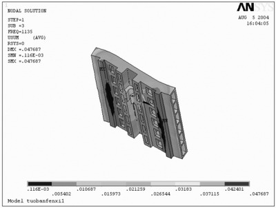
f) ANSYS third-order mode map
Figure 4 The various modes of the carriage
According to the calculation result, the carriage has a third-order mode within 1200 Hz. The mode shape of the first-order mode is the wobble around the Y-axis on both sides of the carriage, the mode of the second-order mode is the irregular torsion of the carriage around the Z-axis, and the mode of the third-order mode is the carriage. The undulating vibration around the Y-axis and the partial torsional vibration of the corners of the carriage. Through the finite element modal calculation, the dangerous working frequency of the machine tool carriage is 500-600Hz.
It can be seen from the calculation results that the natural frequency is above 500 Hz. The overall natural frequency of the machine pallet is higher, away from the normal working frequency, and the rigidity of the carriage is better. The screw seat of the carriage must be supported by the screw of the machine drive system and must have a high structural rigidity. Through the above calculation results, it can be found that the relative displacement of the screw seat vibration is small, the vibration is small, and the local stiffness is high, thereby enhancing the transmission rigidity of the entire feed system of the numerical control machine tool and ensuring the accuracy of the transmission system. In addition, it can be seen from the vibration pattern that although the vibration amount on both sides of the carriage is the largest, since the vibration is a symmetrical vibration along the Y-axis, it can ensure that the table on the carriage has only a slight vertical displacement and does not affect. swing. The milling machine is used for machining spur gears. During the machining process, the vibration of the carriage causes the slight vertical direction of the table to not affect the machining accuracy of the gears, and meets the design requirements of the machine pallets.
By comparison, it is found that the third-order natural frequency values ​​calculated by the two finite element softwares have the largest difference, but the two frequency values ​​differ only by 1.78%, and the calculation results are very close. At present, ANSYS software is widely used for modal calculation of various structures, and its calculation results have strong credibility. Therefore, the results calculated by Pro/MECHANICA software also have high precision.
V. Conclusion
(1) Through the modal analysis of the finite element dynamics model of the machine tool carriage, the first three natural frequencies and vibration modes of the machine tool parts are calculated. Through the vibration mode and animation display, the dynamic performance of the machine tool carriage can be analyzed intuitively, and the weak links of the parts are found, which provides a theoretical basis for the structural design of the machine tool support.
(2) Based on the analysis of some shortcomings of general finite element, this paper puts forward the idea of ​​modal analysis of pallet using Pro/MECHANICA finite element analysis software, and realizes solid modeling and finite element analysis calculation through it. Seamless integration improves the efficiency of finite element analysis. By comparing with the calculation results of ANSYS software, we found that the Pro/MECHANICA finite element modal calculation results also have sufficient calculation accuracy. This provides a new approach to the design of other machine tool supports.
Spiral Welded Steel Pipe,Black Anneal Tube,Spiral Welded Pipes,Welded Steel Pipe
Steel Tubing,Stainless Pipe Co., Ltd. , http://www.czsteelpipes.com