Abstract : Firstly, the principle of measuring the height of light curtain is introduced. An implementation method of height measuring light curtain is given. The system structure and main performance designed by this method are analyzed. Thereby, the interference between adjacent paths is completely solved, and the measurement accuracy is improved.
Key words: single chip microcomputer; measuring light curtain; grading
1 Introduction
Light curtains are one of the more widely used devices in electronic measurement systems. A light curtain can be used to measure a series of data such as the height, length or width of an object on a constant speed conveyor belt to provide corresponding parameters for subsequent electronic systems. This paper presents a light curtain measurement method that uses a single-chip microcomputer to achieve object height measurement.
2 The basic principle of light curtain measuring object height

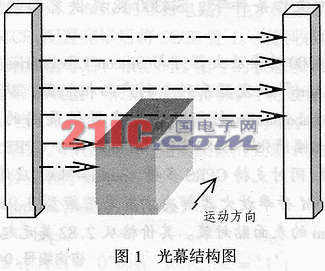
Figure 1 is a schematic diagram showing the structure of a test principle for measuring the height of an object using a common light curtain. In the figure, one side of the light curtain is mounted with a plurality of infrared transmitting tubes at equal intervals, and the other side has the same number of infrared receiving tubes arranged in the same order, and each infrared transmitting tube has a corresponding infrared receiving tube, and is installed in the same On a straight line. When there is no obstacle between the infrared transmitting tube and the infrared receiving tube on the same straight line, the modulated signal (optical signal) emitted by the infrared transmitting tube can smoothly reach the infrared receiving tube. After the infrared receiving tube receives the modulated signal, the corresponding circuit outputs a low level, and in the case of an obstacle, the modulated signal (optical signal) emitted by the infrared transmitting tube cannot smoothly reach the infrared receiving tube, and the infrared receiving tube at this time The modulated signal is not received and the corresponding circuit output is high. When no object passes through the light curtain, all the modulated signals (optical signals) from the infrared transmitting tube can smoothly reach the corresponding infrared receiving tubes on the other side, so that the internal circuits all output low level. In this way, the height information of the object can be obtained by analyzing the state of the internal circuit. Since the upper and lower adjacent optical paths may interfere with each other, the selected infrared light emitting tube has an emission angle of less than 15°. In addition, considering that the light curtain has a certain width, the signal emitted by the infrared transmitting tube should also be modulated. However, in actual production, there are always interferences in the upper and lower paths, and it is difficult to improve the measurement accuracy. In order to completely solve the interference problem of adjacent two channels, this paper presents a method to realize height measurement with C51 single chip and related chips.
3 Height measurement light curtain system structure and working process

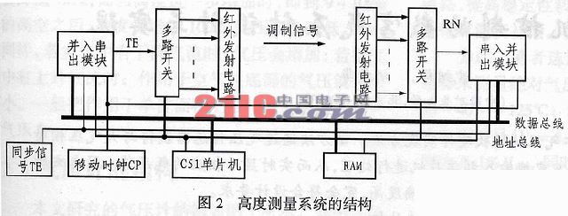
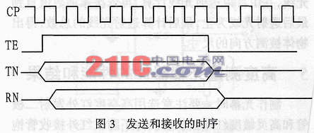
The system structure of the height measuring light curtain is shown in Figure 2. The number of infrared transmitting and receiving paths of the device can theoretically be up to 215. Generally, the height of the light curtain and the spacing between the upper and lower paths are generally not more than 64. For the convenience of introduction, this paper takes the number of channels 16 as an example, and labels the 1st, 2nd, and 3rd channels according to the height of the installation from high to low. ...16 road. The multiplexer for the transmit and receive sections uses a common multiplexer (such as the 7LS15 series). The AO~A3 of the multiplexer of the transmitting end is connected to the P1.0~P1.3 of the single chip microcomputer, and the A0~A3 of the multiplexer of the receiving end are connected to the P1.4~P1.7 of the single chip microcomputer, and are incorporated into the serial output module and the serial input. The parallel module uses 8-bit shift registers (such as 74ILS165 and 74HC595). The load signal LD=P1.4·WR incorporated into the serial module is the data readout signal E=P1.5·RD of the serial-in and parallel-out module. The shift control signal terminates the TE sync signal. RAM is used to store data, which can be connected to the PO and P2 ports of the microcontroller. The size of the capacity depends on the amount of data processed. This article chooses 1KB. The synchronization signal TE and the shift clock CP can be generated by a timer of the single chip microcomputer, and can also be divided by the CP clock by 8 as a TE signal. Both the reading of the serial in and out modules and the writing of the inline and out modules can be done by means of an interrupt. At the same time, the processed serial data can be sent out by using the serial port of the single chip microcomputer. In the linear scan mode, the workflow of the device is as follows: First, after the falling edge of the TE arrives, the MCU writes the data to be transmitted to the serial-in and parallel-out modules, such as 01H, and simultaneously sends the same path selection to the transmitting end and the receiving end. The signal is the first address signal. When the rising edge of TE comes, under the control of the shift clock, the data 01H is sent to the infrared transmission circuit of the first channel through the multiplexer, and then modulated and emitted as an optical signal, and at the same time, infrared The receiving circuit starts to receive when the rising edge of TE comes. Since the multiplex switch selection signals transmitted and received are the same, only one path (i.e., the first path) corresponding to the transmitting end is actually received. The demodulated data can be moved into the serial-in and parallel-out modules under the action of the shift clock, and is received when the falling edge of TE arrives. At the same time, the interrupt processing program of the single-chip microcomputer is triggered, so that the data is read by the single-chip microcomputer. The MCU compares the sent data with the received data. If there is a different concern: only if there is an object blocking in the path, the transmitted signal is not received, resulting in different data sent and received, indicating that the road is Some objects passed. If they are the same, it means that there is no object blocking in the path or the height of the object is lower than the installation height of the infrared transmitting tube. Then scan the second way, and at the same time, after the falling edge of the TE, the MCU sends out the selected address of the second way and sends the data to be sent (this article can also be different with O2H). Similarly, when the rising edge of TE comes, it starts to move out, and through the second way, the transmitting and receiving channels are modulated and then sent out as optical signals. At the same time, the rising edge of TE initiates the second pass. After receiving, the MCU performs related processing. Then there is the third road, the fourth road, ... the fifteenth road, the sixteenth road, thus completing a scan from the first road to the sixteenth road. If scanning is required at a speed of 100 times/s, the frequency of the TE should be 1.6 kHz and the frequency of the shift clock CP should be 12.8 kHz. The timing of transmission and reception is shown in Figure 3. In the figure, RN is the received serial data, and TTTN is the data shifted out by the transmitting end. The waveform of the modem section is omitted from the figure.

In the linear scan mode, the MCU sends the same path selection signal to the transmitting end and the receiving end each time, that is, the first way sends the first way, the second way sends the second way, ... the fifteenth way sends the fifteenth The road is closed, and the 16th road is sent to the 16th road. In the cross scan mode, the MCU sends different path selection signals to the transmitting end and the receiving end each time. That is, the first road sends the second road, the second road sends the first road, ... the fifteenth road sends the 16th road, the 16th road sends the fifteenth road. In contrast, the cross-scan mode measures the height of the object more accurately and has the highest detection accuracy at 1/3 of the center of the detection area. The minimum detection height can be reduced to 2/3 in the linear scan mode.
4 Height detection analysis mode
The light curtain detection mode can have various settings. As can be seen from the above light curtain working process, the first and last light blocking modes and the first and last light transmission modes can be used. In the first and last ray blocking mode, when the object enters the light curtain area, the light is blocked, and the microcontroller will recognize the number of the blocked first ray. Then, the total number of blocked rays is calculated from the bottom up until the last blocked light, and finally the measured direction size of the data object is accumulated. In the first and last ray casting mode, when the object enters the light curtain area, the single chip microcomputer controls the recognition of the transmitted light, and is calculated by the first transmitted light, and then accumulates the value until the last transmitted light, and finally calculates the total number of transmitted light to obtain the object. The size of the direction being measured.
5 Height measurement of light curtain device performance and results
When making a light curtain, pay attention to the use of high-intensity infrared emitting diodes and high-sensitivity infrared receiving tubes. In order to prevent the infrared receiving tube from saturating, a filter may be added to make it work in a micro-conducting state. In the linear scan mode, when the optical axis spacing is 2.5 CM and the light curtain width is 5 M, the maximum resolution is 2.5 CM. When the belt speed (object moving speed) is 5 M/S, the scanning pitch is 1 CM. In fact, the method is also suitable for making high-precision measuring light curtains for use in grading processing equipment such as fruits and parcels.
Square Wire Mesh,Crimped Wire Mesh,Wire Mesh Panels
Weihao Hardware Wire Mesh Products Co., Ltd. , http://www.hsbarbedwire.com
![<?echo $_SERVER['SERVER_NAME'];?>](/template/twentyseventeen/skin/images/header.jpg)